
Views: 0 Author: Site Editor Publish Time: 2026-07-23 Origin: Site
Replacing an air suspension system demands significant resources, yet shops discard a high percentage of replaced units due to misdiagnosis. Symptoms of a failing pneumatic strut—such as a sagging ride height, harsh ride quality, or dashboard warning lights—mirror issues caused by faulty compressors, leaking valve blocks, or defective ride height sensors. To prevent unnecessary expenditures and ensure vehicle safety, technicians and owners must apply a systematic diagnostic framework. This guide details exactly how to test air shock absorber components through visual, dynamic, electronic, and bench-testing protocols to isolate the true point of failure.
Isolate the Sub-Components: An air shock absorber consists of two primary failure points: the pneumatic air spring (prone to leaks) and the hydraulic damper (prone to fluid loss and valve wear). Testing must evaluate both independently.
Prioritize Non-Invasive Testing: Begin with overnight sag measurements, soapy water leak tests, and OBD2 electronic diagnostics before committing to labor-intensive component removal.
Verify Electronic Integrity: Always rule out ride height sensors, relay failures, and compressor output via volt/ohm checks before condemning the physical shock assembly.
Bench Testing is Definitive: The only conclusive method to evaluate the hydraulic damper's internal valving is to remove the unit, depressurize it, and manually test compression and rebound rates.
Table of Contents
Replacing major suspension components without isolating the root cause leads to severe operational inefficiencies. A vehicle owner or fleet manager might replace an entire strut assembly only to find the vehicle still sags the next morning. Often, the actual failure point is a micro-fracture in a plastic airline, a corroded brass fitting, or a damaged ride height sensor wire. Establishing a rigorous testing protocol eliminates this guesswork. You ensure that maintenance efforts target actual failures rather than assumed ones. We see this constantly in the shop. Mechanics throw parts at a problem instead of testing the system. This wastes time and ruins customer trust.
To diagnose the system accurately, you must understand its dual nature. The assembly integrates two distinct mechanical systems. The pneumatic air bladder, typically constructed from reinforced rubber, handles load leveling and ride height. It holds pressurized air supplied by the compressor. The internal hydraulic strut, housed within or alongside the air bladder, controls oscillation and damping. It uses hydraulic fluid and internal valving to absorb kinetic energy. A failure in the air bladder causes sagging and compressor burnout. A failure in the hydraulic damper causes bouncing, poor handling, and tire cupping. Testing must address both systems independently. You cannot assume one side is good just because the other side holds pressure.
Modern vehicles utilize complex Controller Area Network (CAN-bus) architectures. When an air suspension system fails, it rarely triggers just a single suspension warning light. Because ride height affects wheel speed sensor geometry and vehicle stability algorithms, a severe drop in suspension height can trigger a cascade of secondary warnings. Drivers often see Anti-lock Braking System (ABS) deactivated or Traction Control disabled messages alongside the primary suspension fault. Understanding this cascade prevents technicians from chasing phantom brake issues when the root cause is pneumatic. Always read the codes first. Do not start tearing into the brakes when the car is sitting on the bump stops.
Before testing, establish what constitutes a healthy system for the specific vehicle chassis. Normal compressor run times typically range from 15 to 45 seconds upon startup. An acceptable overnight height variance is generally less than 3 millimeters. Rebound rates on a healthy hydraulic damper should be smooth and consistent, returning the rod to full extension without hesitation. Deviations from these baselines indicate a developing fault. Keep a log of these metrics. When a car comes in, compare its current state to the known good baseline. This gives you a clear starting point for your diagnostics.
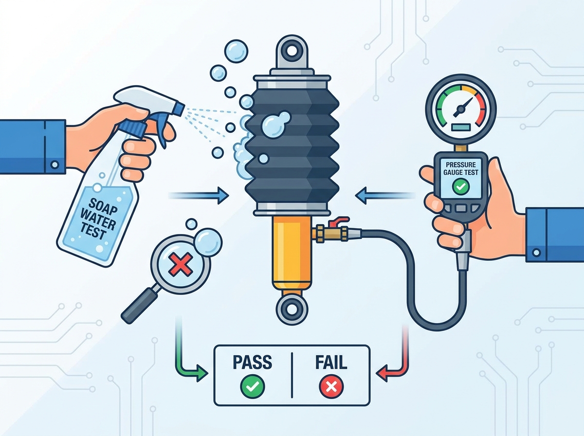
Accurate leak detection requires a clean surface. Road grime, salt, and mud can easily mask micro-leaks in the rubber bladder or around connection points. Safely elevate the vehicle using heavy-duty jack stands. Use a mild degreaser and a soft-bristled brush to clean the air lines, brass fittings, residual pressure valves, and the visible portions of the rubber bladder. Avoid using harsh chemical solvents or wire brushes. These can degrade the rubber and damage nylon air lines, creating new leaks. Spend the extra ten minutes cleaning the components. It saves hours of frustration later when you are trying to spot a tiny bubble.
The overnight sag test is the most reliable non-invasive method for identifying slow pneumatic leaks. Follow these steps exactly to get accurate results.
Park the vehicle on a perfectly level concrete surface.
Using a metric tape measure, record the distance from the exact center of the wheel hub to the bottom edge of the fender lip for all four corners.
Disable the air suspension system. Depending on the vehicle, this involves turning off a dedicated trunk switch, pulling the suspension fuse, or disconnecting the battery. If left active, the module may wake up and auto-level the vehicle, masking the leak.
Let the vehicle sit undisturbed for 12 to 24 hours.
Remeasure all four corners and compare the numbers to your initial readings.
Analyze the data carefully. A drop isolated to a single corner strongly indicates a leak in that specific air spring or its immediate airline connection. A drop across an entire axle often points to a failing central valve block or a leak in the main distribution line rather than the individual struts. We use this test on every air suspension job. It never lies.
Once a specific corner is identified as dropping, pinpoint the leak using a soapy water solution. Mix water with a high-foaming dish soap in a spray bottle. Liberally apply the solution to all air line connection points, brass fittings, residual pressure valves, and crimp rings at the top and bottom of the strut. Do not be stingy with the spray. Soak the connections.
Inspect the rubber air bladder closely. Look for micro-punctures, dry rot, and fold-crease wear. The bladder folds over itself during normal operation, and this crease is the most common failure point. Differentiate between normal condensation and active leaking. A leak will produce continuous, growing, and multiplying bubbles. If you see active bubbling, the pneumatic seal is compromised. Mark the spot with a paint pen so you do not lose track of it.
A perfectly sealed air bag can hide a completely blown hydraulic damper. Perform a thorough visual inspection of the shock body beneath the air bladder. Look for oil weeping, heavy fluid accumulation, or dirt caked onto oily residue. If the hydraulic fluid has leaked out, the internal valving can no longer provide resistance. This renders the damper useless regardless of the air spring's condition. Run your hand along the bottom of the shock tube. If it comes away wet with oil, the damper is dead. You must replace the unit.
The traditional bounce test involves firmly pushing down on each corner of the vehicle and counting the suspension oscillations before it settles. A healthy damper will allow the vehicle to compress, rebound past the center point once, and then settle immediately. While useful for older coil-sprung vehicles, modern adaptive and heavily pressurized air systems often mask a failed damper during a static bounce test. The high pneumatic pressure can make the corner feel stiff even if the internal hydraulic fluid is entirely depleted. Do not rely solely on this test for air suspension. It will fool you.
Dynamic road testing exposes failures that static tests miss. Select a test environment with uneven roads and varied articulation. You need to put the suspension through its paces to see how it reacts under load.
The High-Speed Curve Test: Safely drive the vehicle at highway speeds on a winding, uneven two-lane road. Evaluate the chassis for excessive body roll, floating sensations, and instability under lateral load.
Identifying Damper Symptoms: Look for excessive bouncing after hitting dips, severe nose-diving during hard braking, bottoming out over speed bumps, and a general feeling of disconnection from the road surface. These indicate the hydraulic strut has failed.
Identifying Air Spring Symptoms: Look for harsh, rigid impacts where the vehicle feels like it is riding directly on the bump stops. Listen for continuous or highly frequent compressor cycling while driving, which indicates the system is fighting an active leak.
Mechanical testing must be paired with electronic diagnostics. Connect a professional-grade OBD2 scanner capable of accessing the specific suspension control module. Read all active and stored Diagnostic Trouble Codes (DTCs). Do not just clear the codes and hope for the best. Write them down and analyze what the system is telling you.
Look for specific fault codes such as "Air Suspension Inactive," "Pressure Accumulator Leaks," "Compressor Duty Cycle Exceeded," or sensor communication errors. Interpret cascade DTCs carefully. ABS and traction control codes often act as secondary indicators of a severe suspension height discrepancy rather than independent brake failures.
Use the bi-directional capabilities of the scan tool to force the inflation and deflation of specific corners. Command the front-left strut to add pressure and monitor the live data for the ride height sensor voltage. If the voltage does not change smoothly, or if the corner fails to rise despite the compressor running, you have isolated a valve or sensor issue. This is where a good scan tool pays for itself.
Do not condemn a physical strut without verifying its supporting electronics. Use a digital multimeter to test the ride height sensors. Check for dead spots in the sensor's sweep and ensure signal continuity back to the control module. Verify voltage at the air shock solenoids. If the module is commanding the valve to open but no voltage reaches the connector due to a broken wire, the strut will fail to inflate. This mimics a mechanical failure perfectly. Always check the wiring harness. Rodents love to chew on sensor wires.
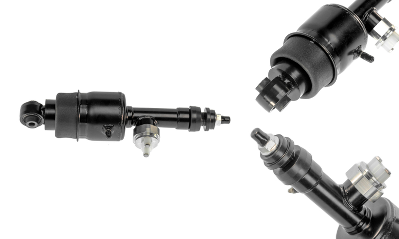
If on-vehicle testing points to a damper failure, the unit must be removed for bench testing. Mandatory safety protocols apply. Never unbolt a fully pressurized air strut. Use the bi-directional scan tool to command a complete deflation of the specific corner. If a scan tool is unavailable, carefully and slowly loosen the airline fitting at the strut to bleed the air pressure manually. Wear safety glasses and keep hands clear of pinch points as the suspension collapses. Treat these systems with respect. The pressure can cause serious injury if released suddenly.
Bench testing is the definitive method to evaluate the internal hydraulic valving. Once removed, secure the air shock absorber safely in a heavy-duty bench vise. Clamp only on the designated lower mounting brackets to avoid crushing the shock body.
Press the damper rod downward with significant body weight. Evaluate the firmness, resistance, and consistency of travel. It should require substantial, steady effort to compress.
If the rod compresses easily with little resistance, or if you feel a dead zone where it drops suddenly before catching, the internal valving is blown.
Release the rod and time the rebound. The high-pressure gas charge inside a healthy damper will force the rod to return to its fully extended position smoothly and relatively quickly.
A rod that stays compressed, moves upward in jerky steps, or extends with zero resistance indicates complete internal hydraulic failure.
Complete replacement is necessary when there is evidence of both hydraulic fluid leakage and air bladder degradation. Furthermore, if the unit fails the manual bench test and is a sealed, non-modular design, the entire assembly must be discarded. Attempting to patch a leaking bladder on a strut with a blown hydraulic damper is a waste of labor. You will just end up doing the job twice. Bite the bullet and replace the whole unit.
Repair is viable when failures are isolated to external, replaceable components. This includes swapping out damaged O-rings, replacing cracked brass airline fittings, or installing new residual pressure valves. On modular units where the hydraulic strut passes the bench test with optimal resistance and rebound, technicians can often replace just the rubber air spring. This preserves the expensive electronic damping strut and saves the customer money.
Consider the long-term reliability of the chassis. Replacing a single shock is mechanically possible, but conceptual trade-offs exist. Suspension components wear at similar rates. If the front-left air bladder fails from dry rot at 80,000 miles, the front-right bladder is likely in a similar state of degradation. Replacing in axle pairs ensures balanced handling, consistent ride height, and prevents the vehicle from returning to the shop a month later for the opposite side. We always recommend replacing in pairs. It is the only way to guarantee a proper repair.
Diagnostic Finding | Component Status | Recommended Action |
|---|---|---|
Overnight sag on one corner; active bubbles at airline fitting. | Pneumatic Leak (External) | Repair fitting/O-ring. Retest. |
Overnight sag on one corner; active bubbles on rubber bladder fold. | Pneumatic Leak (Internal/Bladder) | Replace air spring or entire assembly. |
Fluid weeping on shock body; excessive bouncing on road test. | Hydraulic Damper Failure | Replace entire shock assembly. |
Rod stays compressed during bench test; no rebound. | Internal Gas/Valve Failure | Replace entire shock assembly. |
Scanner shows no voltage change from ride height sensor during travel. | Electronic Sensor Failure | Replace sensor. Inspect wiring harness. |
Working on air suspension systems introduces severe crushing hazards. A vehicle can drop rapidly and unexpectedly when an air line is severed, a valve is opened via a scan tool, or a degraded bladder finally ruptures. Never place hands, arms, or your head inside the wheel well of an air-suspended vehicle that is supported only by a hydraulic floor jack. Mandatory use of heavy-duty, properly rated jack stands is required. Always disable the air suspension control module before lifting the vehicle to prevent the compressor from attempting to level the chassis while it is in the air. Safety is not optional here.
The pneumatic lines run at high pressures. Use correct techniques for safely disconnecting push-to-connect fittings. Press the retention collar inward evenly while pulling the nylon line outward. Forcing or prying the line will score the nylon, guaranteeing a leak upon reassembly. During testing and removal, immediately cap or tape over open air lines and valve block ports. Preventing dirt, water, and shop debris from entering the open pneumatic system is critical. Particulate matter will destroy the compressor rings and jam the solenoid valves. Keep your workspace clean and cap those lines immediately.
Knowing how to test an air shock absorber systematically is the key to identifying the real cause of air suspension problems. By combining visual inspections, leak testing, electronic diagnostics, road testing, and bench testing, technicians can reduce misdiagnosis, avoid unnecessary replacement costs, and ensure long-term suspension performance and vehicle safety.
Working with a trusted suspension parts manufacturer can further improve repair quality and long-term reliability. Tianyi specializes in high-quality air suspension components, including air shock absorbers, air springs, compressors, and complete suspension solutions for passenger vehicles and commercial applications. With reliable manufacturing, strict quality control, and OEM/ODM capabilities, Tianyi helps customers achieve dependable suspension performance worldwide.
Begin every diagnosis with a visual inspection and overnight sag test before removing any components.
Use soapy water and electronic diagnostics to accurately distinguish pneumatic leaks from sensor or compressor faults.
Perform bench testing to verify hydraulic damper performance before replacing the entire assembly.
Replace worn components with high-quality parts that match OEM specifications for reliable suspension performance.
Before selecting an air suspension parts supplier, evaluate their manufacturing experience, product quality, technical support, and supply chain reliability to ensure long-term vehicle safety and performance.
A: Driving with a failed air shock is highly discouraged. A blown air bladder causes the vehicle to ride on its bump stops. This leads to severe impacts that can damage the chassis, suspension geometry, and the air compressor due to constant running.
A: A bad air bag leaks pressure, causing the vehicle to sag overnight or the compressor to run constantly. A bad hydraulic shock loses fluid and internal resistance, causing excessive bouncing, nose-diving, and poor handling, even if the ride height remains normal.
A: Overnight dropping is caused by a pneumatic leak. The most common culprits are dry-rotted rubber air bladders, cracked plastic air lines, leaking brass connection fittings, or a failing central valve block that allows air to escape back through the system.
A: Modern vehicles use shared CAN-bus data. A severe drop in ride height alters the suspension geometry and wheel speed sensor readings. The control module disables ABS and Traction Control as a safety precaution because it can no longer accurately calculate vehicle dynamics.
A: Test the compressor by monitoring its duty cycle and output pressure via an OBD2 scanner. A healthy compressor should fill the system and shut off within 15 to 45 seconds. If it runs continuously, sounds excessively loud, or fails to build specified pressure, it requires replacement.
A: While mechanically possible to replace just one, replacing them in axle pairs is highly recommended. Suspension components wear evenly. If one side fails from mileage and age, the opposite side is usually nearing failure. Paired replacement ensures balanced handling and ride quality.
A: Symptoms include a sagging corner, the vehicle leaning to one side, a harsh and rigid ride, excessive bouncing after hitting bumps, visible hydraulic fluid leaking down the shock body, and continuous running of the air suspension compressor.


